Troubleshooting Manual
Basic Fault Finding Procedure
When troubleshooting your Biasi Combi or System boiler please follow the following safety checks need to be done:
– Gas Supply: verify basic boiler gas supply, check if it is clean and gas has a free passage. Boiler inlet gas pressure level at the gas valve should be set for 20 mbar.
– Electrical Supply: verify if boiler has electrical supply of 230 V, and not 110 V
– Electrical: verify correct electrical polarity; verify the electrical circuits (test the short circuit), verify earth continuity (earth test) and resistance (earth test) earth tests.
Warning! Use only qualified Pro Fit Loyality Club boiler specialist to work on Biasi gas boilers.
Things to remember before using the boiler, after each restart and repair
1.Before lighting the boiler you are advised to have a professionally qualifi ed person check that the installation of the gas supply:
– is of the correct gauge for the flow to the boiler
– is fitted with all the safety and control devices required by the current regulations.
– pressure relief valve is connected and terminated the way it allows necessary and safe discharge. Responsibility for damage caused by pressure relief valve opening and consequent water escape is not manufacturers!
– proper drain pipe is connected to the proper condensate outlet
2. On detecting the smell of gas:
– electrical switches, telephones or any other devices producing energy shouldn’t be operated
– open the windows and doors so that the fresh air can come in and replace condensate gas
– turn off the gas clocks
– get the assistance Pro Fit Loyalty Club service engineer
3. Do not touch the appliance with any parts of your body especially bare feet, hand etc.
4. Never block or modify pipe work or/and condensate outlet
5. In instances where some structural work or maintenance work needs to be performed near the fume exhaust devices or their parts or/and exhaust duct, always turn off the appliance. Once all work is complete have a Pro Fit Loyality Club service engineer check their efficiency once more.
6. All repairs, service and maintenance work (under or over guarantee) must be carried out only by an Pro Fit Loyality Club service engineer using Biasi original spare parts. You shouldn’t do more than turning off your boiler, rest should be done by authorized person.
7. Your will heat the water to temperature chosen bt you in the range of 25/85 degrees (model dependedent), but anyhow it will be less than boiling point
– it needs to be connected to hot water supply and a central heating system , its outputs needs to be compatible, so as performance
– should be used for the purpose for which it was designed for
– be touched by children or by those unfamiliar with its operation
– mustn’t be touched by children or by those unfamiliar with its operation;
– mustn’t be exposed to weather conditions
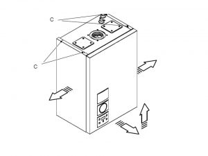
8. During the operation it is quite normal that the boiler produces a white plume of condensation vapour from the flue terminal. This is due to the high efficiency of the appliance. Usually it occurs when there are low teperatures outdoor.
In an Emergency
The moment you suspect water or gas leak you should immediately switch off electrical supply in the house/apartment, next switch off the selector switch on the facia panel. After this you can switch on the electrical supply in the apartment/house back. For safety reasons gas supply should be switched off, you can do it either at the isolating valve or the meter itself . Call your customer support immediately and request service boiler engineer as soon as possible.
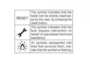
Boiler reset
Warning! RESET will take all parameters back to the factory value. Occurs only by setting “parameter 08=04”. Reset is displayed by switch on of all symbols present on the display.
To reset the boiler hold reset button (11) for 10-15 sec. Button shown on a Control Panel with button descriptions below
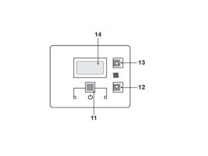
11 Reset/Stand-by/Winter key
12 C.h. temperature reduce key
13 C.h. temperature increase key
14 LCD display
Adjusting the c.h. temperature with the external temp. probe installed (optional feature)
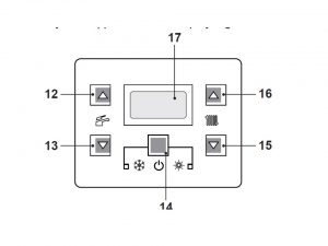
Your boiler will automatically adjust c.h.system water temperature flow when the external temp. probe (optional) is installed in relation to the external temperature. In this case the boiler must be set by a qualified installer. However, if the ambient temperature is not comfortable, the flow temperature of the heating plant can be increased or reduced by ± 15°C by acting on keys 15 (reduce) and 16 (increase)
Timed manual heating function
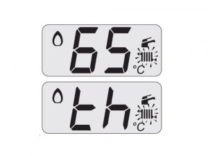
This function allows to manually activate/deactivate the central heating operation for a fixed period of 24 hours. Activation for 24 hours: Pressing keys 15 and 16 at the same time for 2 seconds til you see “th” on LCD screen/display, it will appear together with the “on”
Following, the LCD display shows the main circuit temperature which alternates with the word “th”. The symbol flash
Deactivation/End of function .This function will end when the time set passes or when the function status is set to “oF”. Hold down keys 15 and 16
Adjusting D.h.w. temperature
The temperature of the d.h.w. can be adjust ed by acting on keys 12 (increase) and 13 (reduce) from a minimum of about 35°C to a maximum of about 60°C. Press one of the two keys once to display the “set” value. Press again to access the modification. Signal given by the LCD display: the “set” value of the d.h.w. and the symbol flash. The background of the display will be illuminated.
Adjust the d.h.w. temperature to a value suited to your needs. Reduce the necessity of mixing hot water with cold water. In this way, the automatic adjustment features will be appreciated.If water hardness is particularly high, we recommend that the boiler be adjusted to a temperature less than 50°C. In these cases we recommend however that a softener is installed on the d.h.w. system.
3 star preheating function
This function diminishes consumption of the domestic water supply at the time of withdrawal, preparing the boiler temperature at the requested temperature. To activate the 3 star preheating function press keys 12 and 13 together until the letters “cF” appear on the boiler’s LCD display which alternates with the word “on”
To disable the 3 star preheating function press keys 12 and 13 together (Fig. 2.18) until the letters “cF” appear on the boiler’s LCD display which alternates with the word “oF”.
Warning! Should the power to the boiler fail, wait at least one minute before reactivating the function upon reactivation.
Servicing your Appliance
Per users manual and safety reasons your boiler should be serviced once every year. Your boiler engineer will perform all necessary checks and some cleaning (pipes, burner etc) and well as will check complete boiler functionality. You need to assure that proper ventilation is being provided at all times (never hang out any materials close to or over the boiler), and check house chimney ventilation annually. Standard 230V ~ 50Hz electricy supply is required for all Biasi boilers.
Error codes
The LCD display indications provide help in the diagnosis of fault finding.
Fault finding table for Biasi ActiveA boilers
| RESET; Er 02 | Fault of safety thermostat |
| RESET; Er 03 | Faults classified as “other” |
| Er 04; key | Primary circuit fault ( lack of water or no flow) |
| Er 05; key | Faulty fan control system |
| Er 06; key | Faulty c.h. temperature probe NTC |
| Er 08; key | NTC External temperature probe fault (when fitted) |
| Er 09; key | NTC temperature flue probe fault |
| Er 10; RESET | Flue temperature probe NTC fault (flue temperature under 120 ̊C) |
| Er 14; RESET | Faulty pump (absence of wate flow in the main circuit) or primary temperature above 105 ̊C |
| Er 15; RESET | None or too low water flow; Faulty pump (temp. difference between probes higher than 35 ̊ C) |
| Er 16; RESET | Possible exchange of NTC probes (Flow or Return) or pump wrongly mounted (upside — down) |
| Er 17; RESET | Faulty c.h. temperature probe NTC (Flow or Return) |
| Er 18; RESET | Primary circuit fault (lack of water or not proper flow) |
| L3 | Useful output limitation (temperature difference between probes higher than 25 performing ̊ C) : Boiler test performing |
| Td | Thermostat Delayed : Boiler test performing |
| An 11 | Parasite flame |
Biasi Advance Plus Combi error codes
Biasi Advance Plus Combi error codes include all faults display on LCD as in Biasis ActiveA boiler plus
| erros | meaning |
 |
Boiler Stand-By, hyphens are turned on in sequence to simulate running /antifreeze pro- tection activated) |
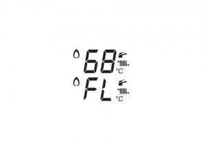 |
Filling request: the boiler works regularly and the display shows all the icons, but the signal FL is flashing every 1 sec. |
 |
Insufficient pressure: the boiler stops displaying the water lack error. |
 |
Boiler waiting for heat request |
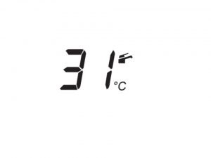 |
Boiler in summer mode (d.h.w.).The primary circuit tem perature is displayed. |
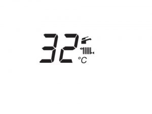 |
Boiler in winter mode (c.h.+ d.h.w.).The primary circuit temperature is displayed. |
 |
Boiler on demand for c.h. power. |
 |
Burner ignition (spark) |
 |
Flame present (Burner on) |
 |
Pre-heating function 3 stars DHW comfort.This information is not displayed. It will be possible to check its state in the section “INFO” value “cF” (the signal “cF” is alternated to the CH temperature value until the end of this function). You can enter the function pushing the buttons 12 and 13 together. The function is confirmed showing ON or OFF alternating for 5 sec.This function is always active at every hour (it’s not possible to set the time slots unless a remote control is connected). |
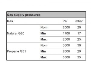
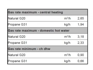
For all Biasi boilers following gas supply pressures are required
For all Biasi boilers following min/max gas rates available
INFO MODE
In case when Authorised Service Centre Engineer needs to be called, it may be useful to use displaying in INFO mode.The INFO mode allows the display of some information on the boiler functioning status. Providing him information from info mode makes sure that we are being understood or what repair needs to be done.
In order to access the INFO mode, press keys 11 and 13 (picture from RESETting section ) at the control panel at the same time. Press it until the letter di appears on the display that alternates with codes below:
| Code | Meaning |
| 01E | Missing burner ignition |
| 02E | Safety thermostat fault |
| 03E | General lockout |
| 04E | Primary circuit fault (no water or flow absence ) |
| 05E | Faulty fan control system |
| 06E | Faulty c.h. temp. probe NTC |
| 08E | Faulty external temp. probe NTC |
| 09E | Faulty flue temp. probe NTC |
| 10E | Flue probe intervention lockout |
| 11E | Flame detection error |
| 14E | No circulation, of faulty pump or intervention primary temperature limit. |
Repair and replacement parts
Biasi boilers repair and replacement parts are being handled by Pro Fit Loyality Club specialists. In order to make sure that all the parts used for repair and replacements, spare parts will be provided from the same manufacturer as the complete boilers. Producer wants to assure that the replacement parts offer exactly the same quality as the original ones. One year guarantee is provided for all the spares.
Safety First!
Initial steps
- Before you start to work on Biasi boilers turn off the thermostat knob . It is located on the control panel cover
- Allow your boiler to cool
- Isolate the electricity supply.
- Turn off the gas at both : the gas valve and at the gas meter.
- Each time when removing and replacing parts involving the draining the system, first close the boiler isolation valves and then drain the boiler using the pressure gauge connection. Warning! You shouldn’t use the safety valve to drain the boiler.
- Each time when removing any items containing water (hoses, pipes etc) make sure they do not spill on electrical components.
- Each time replace easily useable parts like o-rings and gaskets with new parts
- Each time conduct all electrical check: polarity, continuity and resistance (earth test) before and after any work
Warning! Always test for gas soundness after completing any exchange of gas carrying components and carry out functional checks of controls.
Replacement of any component requires the removal of the outer case front panel.
1. Isolate the appliance
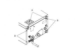
2. First you need to remove the front panel, to do so unscrew screws A (as shown on the picture). After this side panels can be removed easily. by unscrewing screws B and C from the drawing below. Afterwards side panels need to be pulled outside.
3. Re-assemble in reverse order
Warning! Fit the front panel hooking it on the upper side. Push the front case panel until it is completely hold in place. Ensure that the front panel edge is close —fitting to the side panels. Lock in place the panel with the appropriate screws.
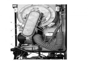
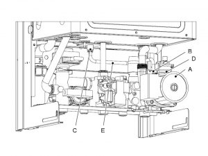
Fan and the Air box replacement
1. Isolate the appliance
2. Gain General Access -remove outer case front panel
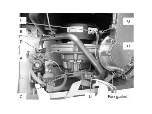
3. Disconnect the rubber pipe C
4. Unscrew the gas connectors D and remove the gas pipe E.
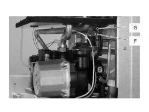
5. Disconnect the connector F
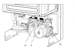
6. Disconnect the fan connector G by pressing the plastic hook placed on the side of the connector.
7. Unscrew the screws H.
8. Remove the fan A with the air box .
9. Remove the screws I and the air box
10. Re-assemble in reverse order
Warning! Before reassembling ensure the fan gasket is correctly mounted. After any service operation on the components of the gas circuit check all the connections for gas leaks.
Ignition and detection electrodes replacement
1. Isolate the appliance
2. Gain General Access -remove outer case front panel
3. Disconnect the connector of the ignition electrodes, detection electrode and the earth wire
4. Unscrew the screws and remove the ignition electrodes and the detection electrode
5. Re-assemble in reverse order
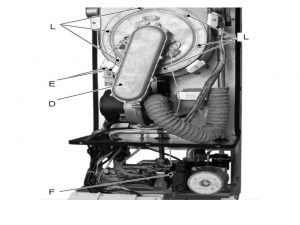
Condensing heat exchanger replacement
1. Isolate the appliance
2. Gain General Access -remove outer case front panel
3. Remove the air box. Next step is to disconnect D- electrode connector as well as disconnect the connector of the ignition electrodes E and disconnect the earth wire F (as shown on the picture below).
4 Disconnect the fan connector G by pressing the plastic hook placed on the rear side of the connector.
5 Unscrew the nuts H and remove the fan burner I
6. Now primary boiler circuit should be emptied
7. Afterwards you will need to disconnect J- C.h temperature from the K- probe connector of the flue temperature .Using pliers, remove the spring L moving it down wards and disconnect the rubber pipe M (as shown on the picture below)
8. Remove the clips N
9. You need to loosen O connection totally and pipe P need to be moved a bit upwards, after this turn it right
10. Disconnect Q and move the R pipe R towards down. Free the pipes R and P from the connection of the Condensing heat exchanger .
11. Unscrew the screws S and remove the clamps
12. Unscrew the screws T and remove the support U
13 In order to completely disconnect the condensing heat exchanger, you need to slide it a bit forward
14. Re-assemble in reverse order in reverse order.
Burner replacement
1. Isolate the appliance
2. Gain General Access -remove outer case front panel
3. Remove the air box and the fan
4. Unscrew the screws I and remove the fan
5. Remove the burner by sliding it forward.
6. Re-assemble in reverse order. Ensure the burner is correctly located by lining up the locating tab
Safety Thermostat replacement
1. Isolate the appliance
2. Gain General Access -remove outer case front panel
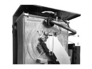
3. Disconnect the wiring B
4. Unscrew the screws C and remove the safety thermostat.
6. Re-assemble in reverse order.
7. Apply an adequate quantity of heat conducting compound between the condensing heat exchanger and the thermostat.
Flue temperature probe NTC and Safety thermal fuse replacement
1. Isolate the appliance
2. Gain General Access -remove outer case front panel
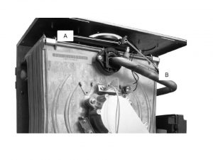
3. Disconnect the connector B from the Flue tem perature probe NTC by pressing the plastic hook placed on the side of the connector.
4. Unscrew and remove the flue temperature probe from the condensing heat exchanger.
5. Re-assemble in reverse order.
Functional lock-out
If the boiler does not function and a code that alternates between the letter Er and the writing RESET appear on the boiler’s LCD display, it shows that the boiler was stopped due to the safety lock-out. You will see that the LCD display will fash as show message as described on the picture below
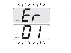
Safety lock-out may occur even in case of a blockage of the condensate drainage. It is highly recommended to verify if condensate drainage pipe and traps are clean. Now you should press button number 14 as shown on he pictures in order to reset boiler and its control panel.
Warning! In case of persistent lock-out call a competent and responsible Service Engineer needed.
Cleaning the condensing heat exchanger and burner
1. Isolate the appliance
2. Gain General Access -remove outer case front panel
3. Remove the sealed chamber lid.
4. Disconnect the connectors of the ignition electrodes E and detection electrode F (as shown on the picture)
5. Disconnect the rubber pipe G
6. Unscrew the gas connector H.
7. Loosen (do not remove) the screw I.
8. Remove the screws J and the air box K. Leave the air box with the air hose clamped to the water pipe.
9. Remove the nuts L (as shown on the picture) and the burner fan group D. If the pressure is lower, take steps to correct the pressure level. The burner does not need special maintenance, but it is sufficient to dust it with a bristle paintbrush.
10. Re-assemble in reverse order
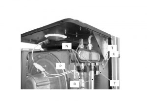
Pump replacement
1. Isolate the appliance
2. Gain General Access -remove outer case front panel
3. Empty the primary circuit of the boiler
4. Extract and lower the control panel
5. Disconnect the connector B (as shown on a picture below)
6. Loosen the connection C, remove the fork D and the pipe E
7. Remove the fork F (as shown on the picture below) and the connection of the capillary pipe of the pressure gauge
8. Uninstall G locking plate
9. Uninstall H connection
10. Unscrew all (should be two) screws, which are holding the pump on its frame. Then remove pump itself.
11. Re-assemble in reverse order. When reassembling the pump, check the correct location of the ring gasket in the inlet port of the pump that seals the connection between the pump and the brass group.
Warning! Prior replacing pump following checks must be done:
– each time check if the pump is not seized and that the movement of the rotor is not subject to mechanical impediments. When the boiler is switched off, remove the front panel. Remove the air release plug of the pump and turn the rotor with a screwdriver
– check the electrical continuity. Only once boiler is switched off, you can remove the front and side case panels and disconnect the connector. Measure the electrical resistance between the pump supply connections. Electrical resistance of the windings (at ambient temperature) must be about 230 Ω
– check the absence of starting defects. Only once boiler is switched off, you can remove the front and side case panels.Remove the air release plug from the pump. Start the boiler and with a screwdriver, turn the rotor in the direction of the arrow. If there is a defect in starting, the rotor will begin to turn normally only starting it manually.
Electronic control P.C.B replacement
1. Isolate the appliance
2. Gain General Access -remove outer case front panel
3. Remove all the wiring connected to the Electronic control/ignition P.C.B. Gently flex the hook located on each side of the socket
4. Remove the adjustment knobs of the spindles of the c.h. and d.h.w. temperature- gently pull them with pliers in the direction shown by the arrow in the picture below
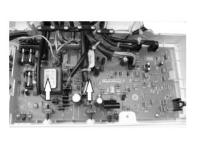
5. Unscrew the four screws that hold the Electronic control/ignition P.C.B on to the control panel.
6. Remove P.C.B control panel by gently lifting its edges. Now free it from wiring if necessary.
7. Re-assemble in reverse order. When reassembling the electronic control/ignition P.C.B it is advised to ensure that the P.C.B is handled with care and held at the edges and with clean dry hands. Fit the P.C.B into the control panel. It can be achieved by putting the edges under control know shafts. You need to make sure that no wiring gets trapped. Afterwards you need to insert spindles in the control panel knobs. Do it till the notch touches the potentiometer edge. It is not necessary to force them in the knob. When you tighten those screws that are fixxing the electronic control/ignition p.c.b. (on the control panel), you need make sure that there is a contact between tap and the boiler reset button.
Warning! After cleaning or replacement as detailed above, if it deemed necessary to undertake a combustion analysis.
Gas valve replacement
1. Isolate the appliance
2. Gain General Access -remove outer case front panel
3. Remove the screw G and disconnect the connector H (as shown on the picture below)
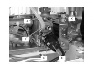
4. Turn off the gas supply and disconnect the gas isolation cock connector from the inlet port of the gas valve.
5. Using pliers, remove the spring I and the rubber pipe J.
6. Unscrew the connector K, remove the fixing fork and remove the pipe. Unscrew the screws and remove the valve
7. Re-assemble in reverse order. Prior new valve fiting you should pre set it. In order to preset it you need to remove the brass plug and turn the plastic screw fully clockwise until it stops. Do not overtight. Turn it counter —clockwise 2 and 3/4 turns. Adjust the gas valve using the fluea nalyser. After any service operation on the components of the gas circuit check all the connections for gas leaks.
Warning! After cleaning or replacement as detailed above, it is deemed necessary to undertake a combustion analysis
Flow limiter installation/ replacement
If the flow rate of the d.h.w circuit is too high it is possible to limit it installing flow limiter. The following sizes are available: 10&12 l/min.
1. Isolate the appliance
2. Gain General Access -remove outer case front panel
3. Unscrew the filer and remove it from the body of the filter
4. Install the flow limiter C as described on the picture below, putting its smaller diameter towards the part B
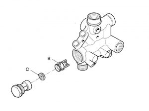
5. Re-assemble in reverse order
Primary circuit pressure switch replacement
1. Isolate the appliance
2. Gain General Access -remove outer case front panel
3. Remove the fixing spring B and remove the primary circuit pressure switch A (as described on the picture)
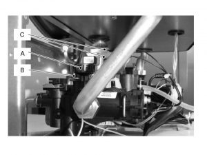
3 Disconnect the connectors C (as seen on the picture).
4. Re-assemble in reverse order
Warning! To lubricate the O ring gaskets you will need to use a grease which is based on silicon and at the same time compatible to be in use with foods. Naturally it should also be accepted by the water Authorities.
Pressure gauge replacement
Before replacement following checks need to be completed:
-turn off the flow and return isolation valves and empty the primary circuit of the boiler
-remove the protective cap from the valve on the top of the expansion vessel and connect a suitable air pressure gauge
-check the pre-load pressure
1. Isolate the appliance
2. Gain General Access -remove outer case front panel
3. Turn off the flow and return isolation valves and empty the primary circuit.
4. Remove the fork H and the probe holder spring I (as described on the picture).
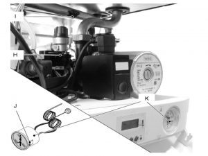
5. Squeeze the tabs J to release the temperature -pressure gauge K and remove it.
6. Re-assemble in reverse order
Expansion vessel and temperature gauge replacement
1. Isolate the appliance
2. Gain General Access -remove outer case front panel
3. Completely unscrew the connection F, the locknut G (as shown on the picture) and remove the expansion vessel from the top of the boiler
4. Re-assemble in reverse order
Noise due to air bubbles are heard during operation- solution
Check that the pressure on the pressure gauge is not below the correct setting. If required, top up the refill the system correctly. Bleed any air present in the radiators, when necessary.
The pressure has gone down- solution
It is necessary to top up the appliance with water again, so as to raise the pressure to an adequate level. If topping up with water has to be done very frequently, system needs to be checked for leaks.
To refill the system first isolate your boiler from any the electrical supply. The filling loop should be reconnected back the way it is demonstrated on the picture below
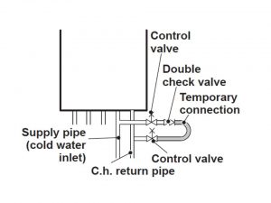
Open the valves of the filling loop and watch the display until it reaches normal filling pressure. The air that will come into the boiler during the filling process will automatically vent through the air purger. Each boiler is fitted with the air purger. In most of the cases large system venting will result in the pressure drop within the system, that is why you should be very careful when venting the air from radiator circuit. Always ensure that the pressure gauge is set at the required pressure.
Warning! If you experience any difficulty with the operation of your boiler, you should switch off the boiler immediately. Boiler should be turned off switch of t the fused spur isolation. Contact your Pro Fit Loyality Club service engineer.
Water comes out of the pressure relief valve
Check on the pressure gauge if the central heating circuit pressure is close to 3 bars. If that is the case, then the temperature will rise in the circuit and it can consequentially cause the pressure relief valve to open. To assure it doesn’t happen again and again you will need to decrese pressure to the normal value. To do so, you will need to vent some of the water extend in the boiler via the bleed valves present on your radiators.
Reduced domestic hot water temperature- solution
Most probable reason is thee impurities caught in the switch of the domestic hot water. Alternatively it can be the limescale deposited in the domestic hot water heat exchanger. It is advisable to have the appliance cleaned out by an authorized service engineer.
No required occasional water leak from the boiler- solution
Shut off the valves , they are located under the boiler and then call an authorized service engineer
Remember! For reasonably economical service install a room thermostat. You shouldn’t shut off the radiator in the area where the room thermostat is installed. In a situation when your radiator/convector does not heath, basic air checks will need to be handled. If no air present the valve opening check needs to be performed. If you feel that the average temperature is too high, do not replace the radiator valves, but reduce the central heating temperature rather.
The anti-freeze system and any additional protections protect the boiler from possible damage due to frost. This system does not guarantee protection of the entire hydraulic system. If cases where outside temperature reaches the 0°C or lower values, we recommended that the whole system is being activated by setting the low temperature on the room thermostat. When boiler is operating in stand by mode, the anti-freeze function can still be activated.